 Quanzhou Ausenist Technology Co., Ltd
 Multi-Pump Booster Project: What to Include in the VFD Control Specification
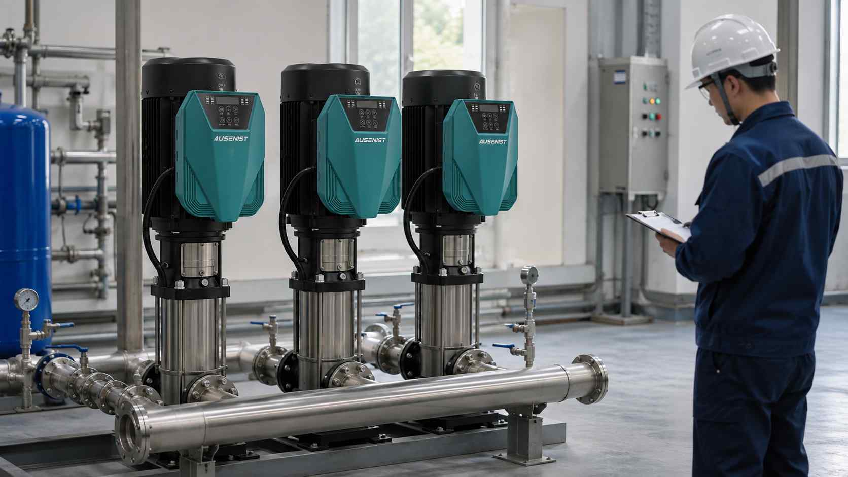
A multi-pump VFD specification should describe how pumps start, stop, alternate, share demand and respond to faults. A statement such as “three pumps with constant pressure” leaves important design decisions unresolved and makes supplier quotations difficult to compare.
Define the operating sequence before choosing the final control architecture. The number of pumps alone does not determine whether one controller, multiple drives, a PLC or additional panel logic is required.
What Information Is Required?
- Nameplate data for every motor, including whether all motors are identical.
- Number of duty, assist and standby pumps.
- Common discharge pressure target and transmitter signal.
- Lead/lag staging conditions and minimum run or stop times.
- Rotation schedule, faulted-pump bypass behavior and manual override needs.
- Required PLC, BMS or RS485 communications and hardwired I/O.
- Panel location, protection level, ambient conditions and cable distances.
Selection Example
A project has four equal pumps: one lead, two lag and one standby. Demand varies throughout the day. When the lead pump reaches its allowed operating threshold and pressure remains below target, the next pump should start. A failed pump should be skipped and an available standby pump called.
The quotation must identify the VFD arrangement, feedback ownership, staging logic, rotation rule and external devices. Each drive is selected from the corresponding motor current and application conditions. The sequence should also define what happens if the pressure signal is lost, because “automatic mode” is not a complete failure response.
Common Mistakes
- Specifying pump quantity but not lead, lag and standby roles.
- Assuming equal motor power means equal motor current and parameters.
- Leaving fault-skip and sensor-failure behavior to site interpretation.
- Adding a PLC without defining which device controls pressure and staging.
- Omitting manual operation and maintenance isolation requirements.
AUSENIST Solution
AUSENIST can review a pump schedule and written sequence to help match YS620 or YS820 options to the project. The review can cover motor matching, pressure feedback, pump staging, rotation, fault handling and the boundary between drive logic and external controls.
The final architecture requires engineering confirmation when motors differ, several communication layers are involved or local safety rules require specific panel functions. AUSENIST should not promise a control sequence that has not been documented and checked. A two-pump project can use the related two-pump VFD control narrative guide.
Send us the motor nameplate, quantity, voltage, application and project requirements. We can prepare VFD selection and quotation.