 Quanzhou Ausenist Technology Co., Ltd
 Pump VFD Specification for Water Treatment Skids and Packaged Systems
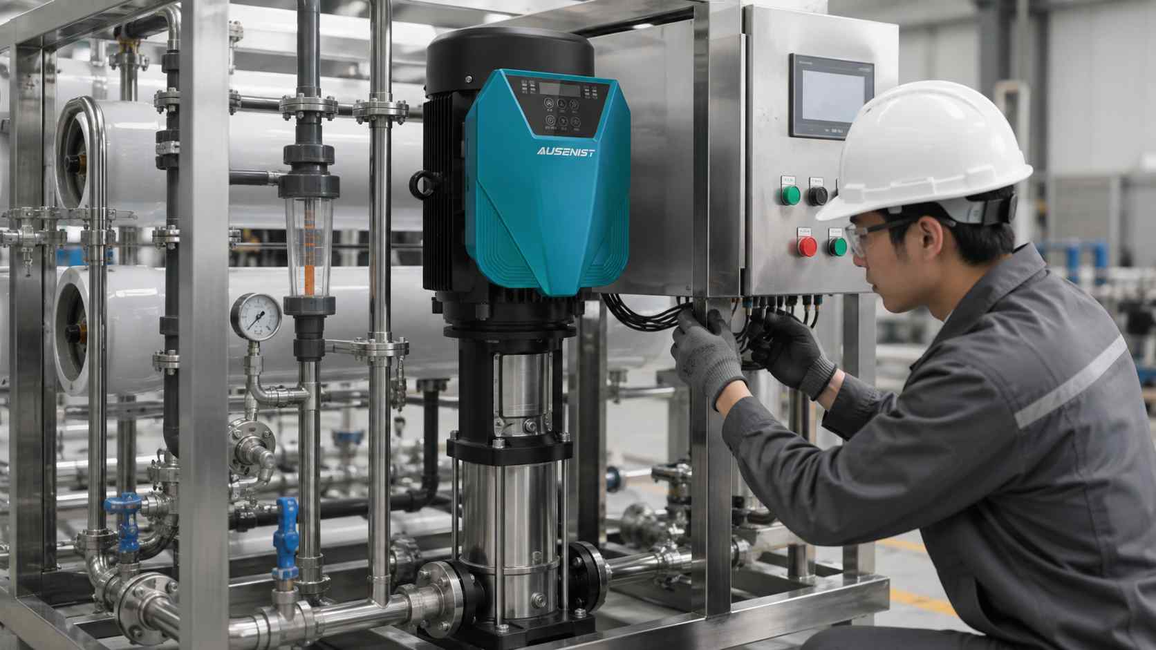
A water treatment skid VFD specification should define each pump duty, motor nameplate, control owner, feedback signal, communications and factory-test scope. This is more useful than asking for a “general water pump inverter,” because packaged systems must be repeatable across production and easy to commission on site.
The skid builder should decide which functions belong in the VFD and which remain in the PLC or package controller before ordering.
What Information Is Required?
- Motor data and pump duty for feed, transfer, circulation or cleaning pumps.
- Supply voltage, phase, frequency and panel distribution arrangement.
- Required speed reference: pressure, flow, level, PLC command or fixed presets.
- Start permissives, interlocks, alarm outputs and emergency-stop boundary.
- Analog-signal ranges, digital I/O and communication protocol.
- Enclosure environment, cable length and required document language.
- Quantity per skid, production forecast and factory-acceptance requirements.
Selection Example
A packaged filtration skid uses one 4 kW feed pump and one 2.2 kW cleaning pump. Both are 380 V induction motors, but their nameplate currents and control duties differ. The PLC sends a speed reference to the feed-pump drive and starts the cleaning pump only during a defined sequence.
Each VFD should be selected from its own motor current and operating conditions. The I/O schedule must state the speed reference, run command, permissives and alarm feedback. A factory test should verify the approved parameter set and interface rather than copying one configuration to both motors.
Common Mistakes
- Using one parameter file for pumps with different motors or duties.
- Duplicating pressure control in both PLC and VFD without clear ownership.
- Leaving analog-signal scaling for site commissioning.
- Omitting parameter revision control across repeated skids.
- Assuming the panel enclosure removes all thermal and environmental limits.
AUSENIST Solution
AUSENIST can review the motor schedule, I/O list and skid control narrative, then propose YS620 or YS820 configurations for engineering approval. Support can include model matching, basic parameter templates, interface requirements and repeatable configuration records for production.
The exact communication, certification, enclosure and test scope must be agreed for each project. AUSENIST should not confirm compatibility when the PLC interface, motor type or required approvals remain undefined.
Send us the motor nameplate, quantity, voltage, application and project requirements. We can prepare VFD selection and quotation.