 Quanzhou Ausenist Technology Co., Ltd
 Sewage Pump VFD Project: Sensor, Alternation and Fault-Skip Requirements
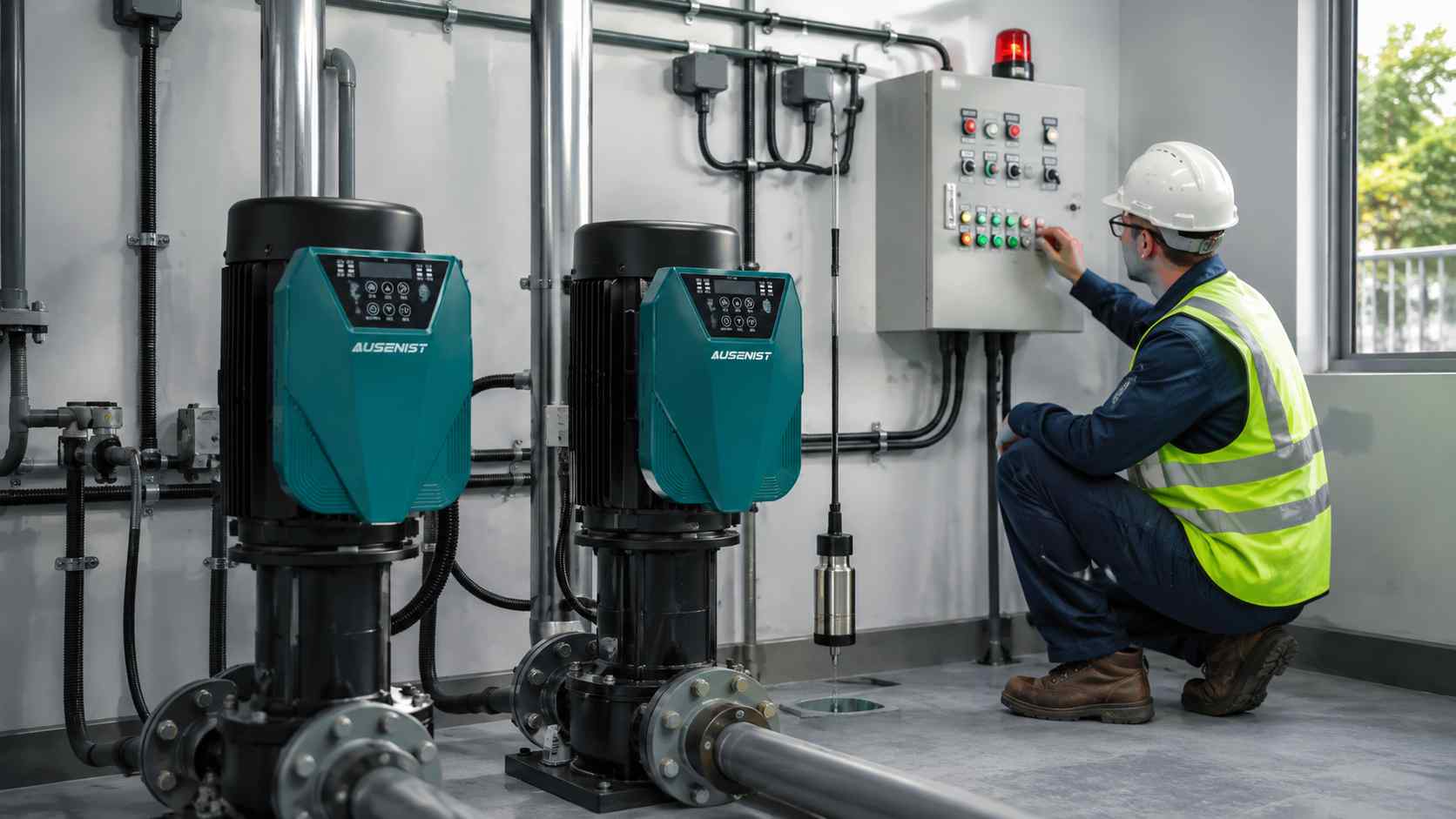
A sewage pump VFD project should define level sensing, minimum permitted speed, pump alternation, high-level response and fault-skip behavior before selecting the control architecture. Variable speed can manage inflow, but low-speed operation must remain compatible with the pump and solids-handling duty.
The VFD is one part of the lift-station system. Level instruments, check valves, wet-well design and emergency operation still require project engineering.
What Information Is Required?
- Motor nameplates, pump curves and solids-handling limitations.
- Number of duty and standby pumps and whether motors are identical.
- Wet-well operating levels and level-sensor or switch arrangement.
- Required alternation, assist-pump and high-level logic.
- Minimum speed, cleaning cycle or full-speed flushing requirements from the pump supplier.
- Fault outputs, faulted-pump skip, local/manual operation and alarm destination.
- Cable lengths, enclosure environment and power-failure restart policy.
Selection Example
A lift station has two 7.5 kW, 380 V pumps arranged duty/standby. A level transmitter provides the normal speed reference, while independent high-level switches request emergency operation. The pumps must alternate after each completed cycle, and a faulted duty pump must be skipped.
Each VFD is checked against its motor current and installation conditions. The control narrative defines normal level control, alternation, high-level override, sensor-loss response and manual mode. The minimum operating frequency is set only after the pump manufacturer confirms the acceptable solids-handling range.
Common Mistakes
- Running too slowly without confirming self-cleaning requirements.
- Using one level signal with no independent high-level protection strategy.
- Describing “automatic alternation” without defining the trigger.
- Failing to specify what happens after a drive or sensor fault.
- Allowing automatic restart without reviewing site safety and wet-well conditions.
AUSENIST Solution
AUSENIST can review the motor data and control narrative, then help match YS620 or YS820 options to the required feedback, alternation and fault-handling functions. The quotation basis can identify external sensors, panel logic and parameter assumptions.
Final settings require confirmation from the pump curve, sewage characteristics and local safety design. A VFD should not be presented as a cure for clogging, incorrect wet-well geometry or unsuitable pump selection.
Send us the motor nameplate, quantity, voltage, application and project requirements. We can prepare VFD selection and quotation.