 Quanzhou Ausenist Technology Co., Ltd
 SEO Title
5.5kW 380V VFD Control for a Two-Pump Sewage Lift Station in Chile
Meta Description
A 5.5kW 380V two-pump sewage lift station VFD selection case for Chile, covering pump alternation, level control, fault handling and motor current checks.
Suggested URL Slug
/5-5kw-380v-two-pump-sewage-vfd-chile/
5.5kW 380V VFD Control for a Two-Pump Sewage Lift Station in Chile
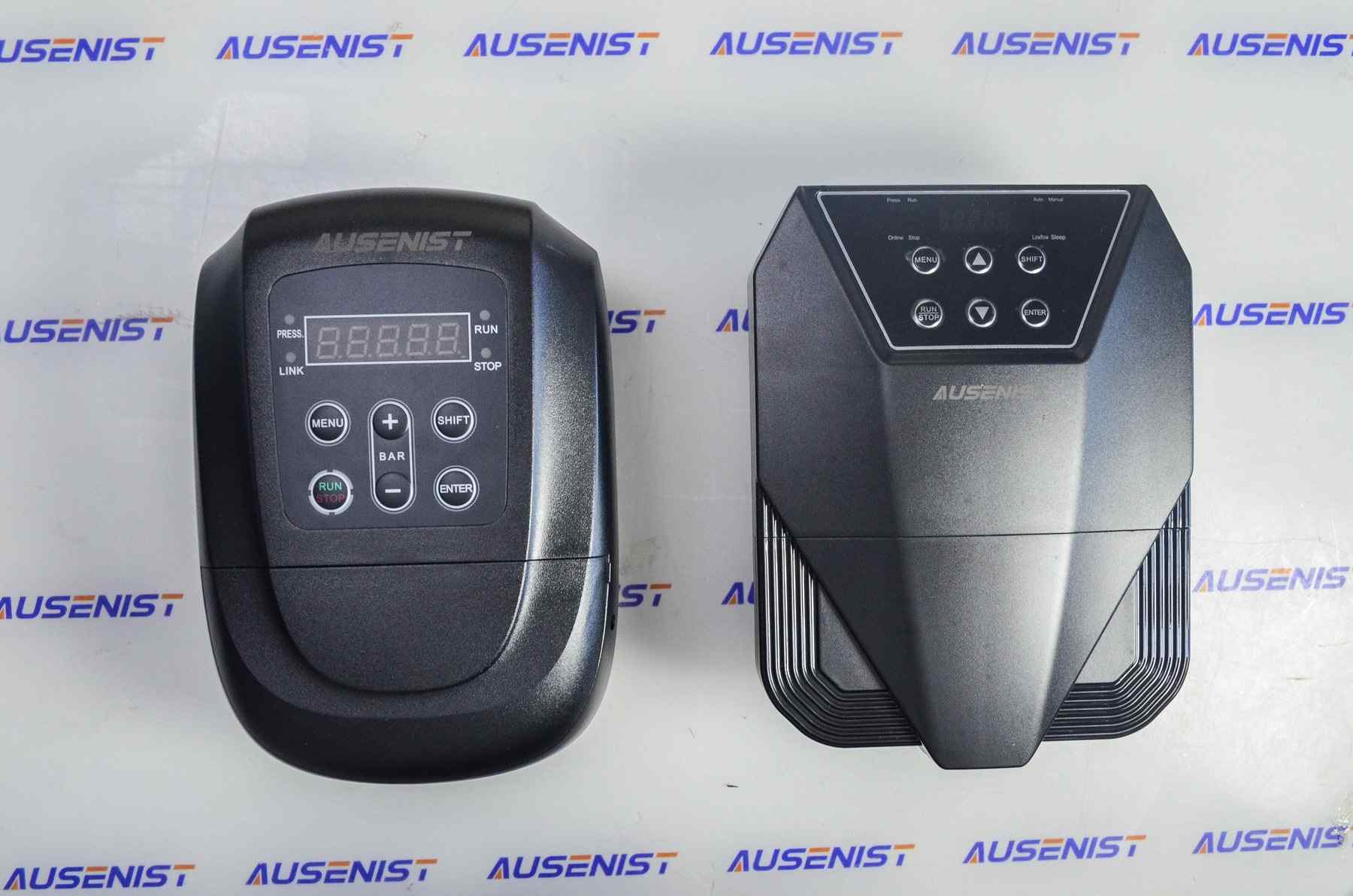
Real AUSENIST product photo used for technical reference; it is not presented as the customer site photo.
Introduction
A wastewater contractor in Chile needed a VFD control solution for a sewage lift station using two 5.5kW pumps. The project requirement was to support controlled pump operation and define how the pumps should alternate, start, stop and respond to a fault.
Based on the project information available for this draft, AUSENIST recommended one matched pump VFD per motor, with the control sequence confirmed against the level control device and panel design. Because actual motor rated current and feedback details were not provided, the final selection requires nameplate and control review.
Project Overview
| Item | Project Requirement |
|---|---|
| Country | Chile |
| Customer Type | Wastewater contractor |
| Application | Sewage lift station |
| Pump Type | Sewage pump |
| Motor Power | 5.5kW each |
| Motor Voltage | 380V three-phase |
| Power Supply | 380V three-phase |
| Number of Pumps | Two pumps |
| Control Requirement | Alternation and fault-aware operation |
| VFD Model | AUSENIST 380V pump VFD, 5.5kW class for each motor |
| Control Method | Level-based start/stop with coordinated pump logic |
Customer Requirement
The customer needed more than simple motor starting. In a two-pump sewage station, one pump may operate as duty pump while the other remains standby or assist pump. The control should balance usage and prevent the whole station from depending on one pump.
The buyer also needed a clear selection basis for whether one VFD could control both motors. For this application, the safer recommendation is normally one VFD per pump motor, because each motor needs separate protection, current monitoring and fault isolation.
Technical Challenge
Sewage pumps do not behave like clean-water pressure pumps. They may face variable solids loading, higher starting torque demand and clogging risk. If both motors are connected to one VFD output, the drive cannot identify which motor has abnormal current or mechanical drag.
The control logic also depends on the level instruments. Float switches, level transmitters or an external controller may be used. The VFD selection must match the final control architecture instead of assuming the drive alone will replace every panel function.
VFD Selection
Based on the information provided by the customer, AUSENIST recommended one 5.5kW 380V pump VFD for each 5.5kW sewage pump motor, subject to rated current confirmation. This provides individual motor protection and makes it easier to skip a failed pump or isolate a pump for service.
The following points should be checked before quotation:
- Motor rated current for each pump.
- Required duty/standby or duty/assist sequence.
- Level switch or level transmitter type.
- Alarm and fault output requirements.
- Whether bypass or manual emergency operation is required in the panel.
Recommended Solution
| Item | Recommended Configuration |
|---|---|
| VFD Model | AUSENIST 380V pump VFD, 5.5kW class for each pump |
| Rated Power | 5.5kW per motor, subject to motor current confirmation |
| Input | 380V three-phase |
| Output | 380V three-phase |
| Control Mode | Level-based pump control with alternation |
| Feedback | Float switch or level transmitter according to panel design |
| Optional Accessories | External relays, panel indicators, bypass circuit or communication as required |
The system can be designed so Pump 1 and Pump 2 alternate as lead pump. If the level rises further, the second pump may assist if the hydraulic design allows it. If one pump trips or is unavailable, the control logic should skip that pump and call the remaining pump where safe.
System Operating Logic
Level signal rises
↓
Lead pump starts through its VFD
↓
Level continues rising if demand is high
↓
Assist pump starts if configured
↓
Fault signal triggers alarm and pump-skip logic
Recommended Initial Parameters
| Parameter | Recommended Setting |
|---|---|
| Motor Rated Power | 5.5kW for each pump |
| Motor Rated Voltage | 380V |
| Motor Rated Current | Set separately for each motor nameplate |
| Maximum Frequency | According to motor and pump rating |
| Minimum Frequency | Confirm according to sewage pump hydraulic requirement |
| Acceleration Time | Set to reduce mechanical and hydraulic shock |
| Deceleration Time | Adjust to avoid abnormal stopping behavior |
| Control Source | Level device, external controller or terminals as designed |
| Fault Output | Configure according to panel alarm requirement |
Final settings should be adjusted according to the actual motor nameplate, pump curve and site conditions.
Expected Operating Behavior
The system is expected to start pumps smoothly, alternate pump duty and improve fault identification compared with a shared-drive arrangement. One failed pump should not automatically remove both motors from control if the panel is designed for independent drives.
No verified running data was provided, so this article does not claim site performance, service life improvement or energy-saving percentage.
Engineering Notes
- Use one VFD per sewage pump when independent protection and alternation are required.
- Confirm whether the station uses float switches or a continuous level transmitter.
- Sewage pump clogging risk should be considered in fault and alarm design.
- Do not switch motors on a live VFD output without an approved control design.
- Motor current should be recorded separately for each pump during commissioning.
FAQ
Can one VFD control two sewage pump motors?
It may be possible only in limited shared-output designs, but it is normally not recommended for a two-pump lift station that needs alternation and fault isolation.
Why use one VFD per pump?
One VFD per motor provides separate current measurement, protection, alarms and control. This makes pump alternation and failed-pump skipping easier to design.
What feedback is used in a sewage lift station?
Float switches or a level transmitter may be used. The correct choice depends on the required control sequence and panel design.
Is PID pressure control required?
Usually no. Sewage lift stations are commonly controlled by liquid level, not pressure.
Have a Similar Pump Application?
If you are selecting a VFD for a centrifugal pump, booster pump, irrigation pump or constant-pressure water system, send us:
- Motor nameplate
- Pump type
- Motor power
- Rated voltage and current
- Power supply
- Number of pumps
- Control sequence
- Application conditions
AUSENIST can recommend the appropriate VFD model and control configuration.
Target Keywords:
5.5kW sewage pump VFD, two pump VFD control, sewage lift station VFD, pump alternation VFD, VFD for sewage pump, pump inverter Chile
Character Count:
Approximately 8,100 characters.