 Quanzhou Ausenist Technology Co., Ltd
 Two-Pump VFD Control Narrative for System Integrators
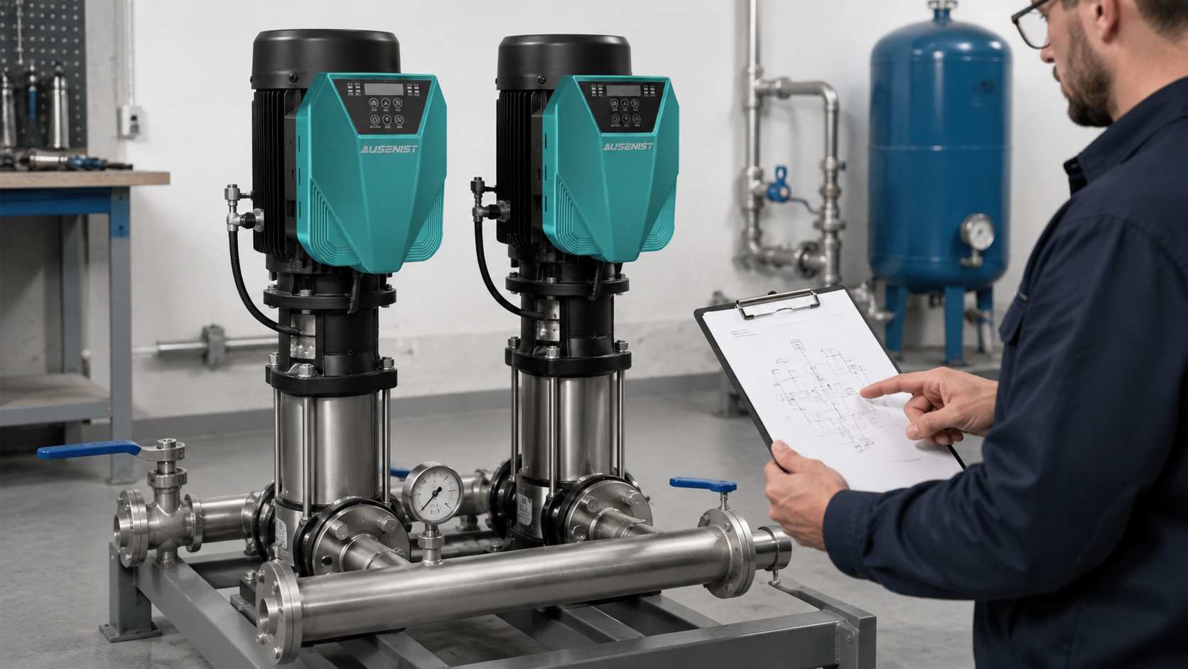
A two-pump control narrative should state whether the pumps operate as duty/standby or duty/assist, how the lead pump changes, when the second pump starts, and what happens after a fault or feedback failure. Without these rules, different suppliers may interpret the same project in incompatible ways.
Write the sequence in operating states rather than relying on labels such as “automatic cascade.”
What Information Is Required?
- Both motor nameplates and confirmation that the pumps are hydraulically compatible.
- Required arrangement: duty/standby, duty/assist or alternating duty.
- Pressure, flow or level feedback signal and setpoint limits.
- Conditions and delays for starting or stopping the second pump.
- Alternation trigger: elapsed time, completed cycle, start count or operator command.
- Fault-skip, sensor-failure, manual mode and power-recovery behavior.
- PLC/BMS interface, remote alarms and panel responsibility.
Selection Example
Two equal booster pumps maintain a common discharge pressure. Pump A starts as lead. If it reaches the defined operating condition and pressure remains low for the approved delay, Pump B starts as assist. When demand falls, Pump B stops after its minimum run time. The lead assignment changes after a completed operating period.
The narrative must also state that a faulted lead pump is unavailable and the healthy pump may take over only within its own hydraulic capacity. Both drives are sized from their motor currents and site conditions. A single pressure signal needs an explicitly defined owner and failure response.
Common Mistakes
- Mixing duty/standby and duty/assist terminology.
- Starting the second pump from frequency alone without a pressure or demand condition.
- Omitting minimum run, stop and staging delays.
- Alternating pumps without defining when alternation occurs.
- Assuming one healthy pump can always satisfy full design demand.
AUSENIST Solution
AUSENIST can review the two motor nameplates and the proposed state sequence, then recommend a YS620 or YS820 control direction for engineering confirmation. Support can cover pressure feedback, alternation, assist staging, fault handling and the division of functions between drives and external controls.
Projects with unequal pumps, separate headers, complex PLC ownership or mandatory redundancy need individual engineering. If the sequence is not approved by the integrator and end user, the quotation should remain conditional. For larger systems, use the multi-pump booster VFD specification guide.
Send us the motor nameplate, quantity, voltage, application and project requirements. We can prepare VFD selection and quotation.