 Quanzhou Ausenist Technology Co., Ltd
Three-Pump Lead, Lag and Standby VFD Control Logic
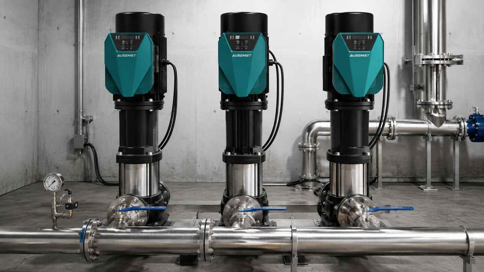
Engineering reference image; project roles and thresholds must be documented.
In a three-pump lead-lag-standby system, the lead pump maintains pressure, the lag pump assists during high demand, and the standby pump replaces an unavailable unit. “Standby” must be defined against peak flow: if all three pumps are required at design demand, the third pump is not true standby capacity.
Control Sequence
| Condition | Required Action |
|---|---|
| Normal demand | Lead pump regulates pressure by PID |
| Pressure low and lead near upper limit | Start lag pump after confirmation delay |
| Demand falls | Stop lag pump after separate delay |
| Lead fault | Healthy permitted pump assumes lead role |
| Scheduled rotation | Change lead assignment at a stable operating point |
| Sensor failure | Apply the agreed safe speed/stop response and alarm |
What Must Be Confirmed?
- Required flow with one, two and three pumps.
- Which pump is reserved as standby.
- Rotation rule: time, start count or calendar schedule.
- Add/drop thresholds and anti-cycling delays.
- Behavior after drive, motor, sensor or communication failure.
Selection Logic
Use one VFD per pump and size each by motor current. Separate hydraulic demand logic from equipment availability. A pump that is isolated for maintenance must not be called. Rotation should balance hours without transferring during unstable pressure conditions.
Common Mistakes
- Calling a pump standby when it is needed for peak capacity.
- Using vague instructions such as “start pump two when needed.”
- Rotating pumps during an active pressure transient.
- Treating every fault as a reason to reset automatically.
AUSENIST Solution
AUSENIST can configure YS620 or YS820 roles, addresses, staging delays, rotation and fault-skip behavior after reviewing the written control narrative. Final behavior must be proven by a witnessed sequence test.
FAQ
Are lead and duty pump the same term?
They are often used similarly, but the project specification should define its terms.
Must the standby pump remain stopped?
It can participate in scheduled rotation while still preserving standby capacity.
What should happen after a communication fault?
The response must be defined: local pressure control, safe fixed operation or stop and alarm.
Related AUSENIST Pages
Send us the pump capacities, motor nameplates and desired sequence. We can convert them into a parameter and acceptance checklist.